Electronic Circuit Diagrams

Introduction
Electronic circuit are usually edited using a graphical schematic capture software integrated in an Electronic Design Automation software suite (for example Kicad) featuring at least a DRC rule checker and a PCB editor, and sometimes a circuit simulator.
However we need sometimes to generate a high-quality diagram of a circuit with additional labellings. We can of course use our schematic capture software to do that, but we can also use instead a graphical language and a diagram generator.
We will present two graphical languages which are integrated within LaTeX:
- Circuit_macros (dpic)
- PGF/Tikz and CircuiTikz
But there is also these graphical languages:
An exhaustive list can be found in CTAN.
LaTeX has nothing to do with diagram layout, but TeX has all the algorithms to render labels without any limitation. It is why we will focus on tools using LaTeX for labels.
We will first present shortly all these packages.
Pstricks is a LaTeX package which provides a graphical layer based on the PostScript language. Despite PostScript was a powerful graphical language, it is now superseded by PDF which is a more portable and efficient document format. The main difference between PostScript and PDF is the former is a true programming language while PDF is just a graphical description of a page.
The PGF LaTeX package is the counterpart of Pstricks for PDF output using the pdflatex program. PGF benefits from the PDF features, but it does not have the programming power of the PostScript language. Tikz is a higher level on top of PGF.
The dpic interpreter used for Circuit_macros can generate diagrams in both Pstricks and Tikz.
Metapost is a language derived from the Donald Knuth's Metafont language, which is processed by an interpreter that produce diagrams in PostScript and work close together with Latex to render the labels.
Asymptote is a vector graphics language that was designed to overcome the Metapost limitations. The interpreter work in a similar way than Metapost. Asymptote can generate diagrams in PostScript, PDF and SVG.
Both PGF and Asymptote are powerful tools to produce diagram. Asymptote is more suited for complicated computation while PGF does not require an external interpreter. However Asymptote does not have a circuit diagram library up to now. It is way we will focus on Circuit_macros and circuitikz.
You have to install LaTeX and the pgf package. On Fedora, install these RPM packages:
- texlive
- texlive-pgf
Circuit_macros
Circuit_macros is a set of M4 macros written by Dwight Aplevich that generate a diagram in dpic language.
M4 is a general purpose macro processor designed by Brian Kernighan and Dennis Ritchie. It is an historic software available in all Unixes and Posix compliant systems. It is mainly used nowadays by Autoconf. While I am not fan of it in the context of Autoconf, I feel it confortable in the context of Circuit_macros.
Pic is a language for typesetting graphics developped by Brian Kernighan. Dpic is an interpreter of a Pic language variant developed by Dwight Aplevich. The dpic interpreter can generate diagram in PostScript, Pstricks, PGF, SVG and many other formats.
The documentation is available here:
Installation
To install Circuit_macros, we have first to download the dpic source, extract the archive and compile the source by running the make command in the extracted directory. The Makefile will generate the dpic standalone executable that should be installed manually in the /usr/local/bin directory for example, so as to be in the standard search path.
Then we have to download the Circuit_macros archive and extract its content somewhere. The boxdims.sty file must be installed in your local texmf directory ($HOME/texmf). And the M4 files can be installed in the directory $HOME/texmf/Circuit_macros for example.
If necessary you will have to set the environment variable TEXMFHOME for LaTeX, for Bash use:
export TEXMFHOME=$HOME/texmf
A Script to wrap all the process
This Bash script, so called circuit-macros-generator, contains all the required commands to generate a PDF document and a PNG image of the circuit:
#! /bin/bash

####################################################################################################

input=$(realpath $1)
input=${input%.m4}

####################################################################################################

m4_path=$HOME/texmf/Circuit_macros
density=300
transparent=white

####################################################################################################

tmp_dir=$(mktemp -d)
echo $tmp_dir

cat > ${tmp_dir}/picture.tex <<EOF
\documentclass[11pt]{article}
\usepackage{tikz}
\usetikzlibrary{external}
\tikzexternalize
\pagestyle{empty}
\begin{document}
EOF

m4 -I${m4_path} pgf.m4 libcct.m4 ${input}.m4 | dpic -g >> ${tmp_dir}/picture.tex
if [ $? -gt 0 ]; then
  echo Error
  pushd ${tmp_dir}
  rm picture*
  rmdir ${tmp_dir}
  exit 1
fi

cat >> ${tmp_dir}/picture.tex <<EOF
\end{document}
EOF

pushd ${tmp_dir}
# cat picture.tex
pdflatex -shell-escape picture.tex
cp picture-figure0.pdf ${input}.pdf
rm picture*
popd
rmdir ${tmp_dir} # more safe than a rm -rf

convert -density ${density} -transparent ${transparent} ${input}.pdf ${input}.png
We use the PGF output of dpic so as to generate a PDF using pdflatex.
Example
As an illustration of the language, we will make a diagram of a simple rectifier circuit:
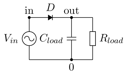
.PS
cct_init(SIdefaults) # initialise and use metric unit
linethick_(.5) # line thickness
define(`dimen_', 10) # component size
elen = dimen_*3/2
Origin: Here
  # go up and draw the source and the in label
  source(up_ elen, AC); llabel(,V_{in},); dot; "in" above
  # turn right and draw the diode
  diode(right_ elen); llabel(,D,)
  # draw the out label
  dot; "out" above
  { # save the current position
    # go down and draw the capacitor
    capacitor(down_ to (Here,Origin)); rlabel(,C_{load},)
    # draw the 0 label
    dot; "0" below
  }
  # draw a forward horizontal line
  line right_ elen*1/2
  # go down and draw the resistor
  resistor(down_ Here.y-Origin.y,,E); llabel(,R_{load},)
  # draw a backward horizontal segment
  line to Origin
.PE
To generate the diagram, we have to run the following command using our script:
circuit-macros-generator simple-rectifier.m4
As you can read in the commented code, the description of the circuit follow the conponents along the two loops. This way is quite natural.
If we want to be perfect, we can scale up the diode and use some hacks to enhance the line corners using a very small segment:
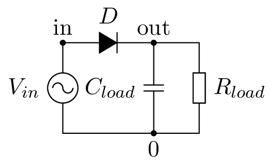
.PS
cct_init(SIdefaults)
linethick_(.5)
define(`dimen_', 10)
elen = dimen_*3/2
epsilon = 1e-3
define(`bigdiode',
  `resized(2., `diode', $1)')
Origin: Here
  source(up_ elen, AC); llabel(,V_{in},); dot; "in" above
  bigdiode(right_ elen); llabel(,D,)
  dot; "out" above
  {
    capacitor(down_ to (Here,Origin)); rlabel(,C_{load},)
    dot; "0" below
  }
  line right_ elen*1/2 then down epsilon
  resistor(down_ Here.y-Origin.y,,E); llabel(,R_{load},)
  line down epsilon then to Origin then up epsilon
.PE
PGF has also this drawback, but is not always perceptible.